What is uMIDI?
uMIDI is a small general purpose micro-controller board built to receive, forward and send MIDI messages accompanied by a (soon to become ;-) quite sophisticated software library / framework. You can use uMIDI for virtually everything you can think of involving (but not limited to) MIDI:
- MIDI merging / splitting
- MIDI controllers (trigger pads, pedals, sequencers, ...)
- MIDI-controllable devices (Guitar/Bass/Synth effects, possibly visual effects)
- and the list goes on...
The board is also equipped with a mini USB port, which in conjunction with the serial communication module allows you to connect the board to your PC as a character device.
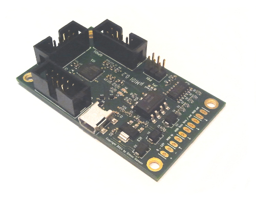
Hardware features
- receive / forward / send arbitrary MIDI messages
- control interface via USB character device
- 24 GPIO ports with special functions:
- 1x SPI
- 2x UART
- 8x ADC
- 2x DAC
- 6x PWM
- 4 GPIO ports connected to solder jumpers
- 2 LEDs (red + green)
See also:
Software library
uMIDI comes with a quite sophisticated high-level software library and framework, which enables you to accomplish most basic tasks very quickly. You can find the documentation of the API at software/src/lib - if you intend to simply use the library as-is, looking at the header files should suffice.
The framework features easy to use device initialization routines which provide an abstraction from the hardware. You just need to specify, which features (GPIO, ADC, PWM, ...) you want to use and how they should be set up with a set of configuration structs and pass those to the initialization routines - no bit-masking / -shifting or other error-prone steps required. It is recommended to keep all your configuration structures in one file - this way you have one single place, where all hardware-related information can be found.
Background tasks whose call-frequency may jitter to some extend can be implemented very comfortably using the background tasks module. The module uses "system ticks" from a CPU timer to schedule registered tasks at three different base frequencies. Of course you can use a counter to further divide down the call-frequency of a specific task.
The two on-board LEDs can be controlled by the corresponding LEDs module. The LEDs can be in one of three modes (static, blinking or flashing once), which are managed by a background task. You can set the mode and/or (in static mode) toggle LEDs manually via service functions. This can be done separately for each LED or for both LEDs at the same time.
The GPIO module is dedicated to.. well.. the GPIO pins. It offers service procedures to set and poll GPIO pins and an easy way to configure all pins with a single data structure.
If you want to implement some kind of modulation with a specific waveform like a sine or triangle wave, you should look into the wave module. This module lets you define waves - again via configuration structures - in terms of waveform, frequency, amplitude and offset. A special background task can then be used to periodically update the output value of a wave. You can even register one wave to react to tap tempo events, in which case a second background task listens for such events and updates the registered wave's frequency accordingly.
Some non-trivial waveforms are not computed from scratch every time - they are read from lookup tables, which are generated during the build process by a small PERL script. These tables also contain "linear to logarithmic" and "linear to exponential" translations in case you need them. The x-resolution of the tables is fixed at 100 values, but you can adjust the amplitude resolution of the log/exp lookup tables in the Makefile, if you need to. In order to do this, you just have to change the LOOKUP_TABLES_YRES variable in the Makefile.
The lookup tables can also be used in conjunction with the PWM module. In fact, the logarithmic and exponential functions are intended for this. You can use a linear MIDI expression value to drive a PWM output exponentially. This may come in handy, as loudness for example is perceived logarithmically. The samples in the exponential / logarithmic tables can be used directly as counter compare values for a 10 bit PWM - if you have to configure your PWM for a different counter resolution, you may have to adjust the amplitude resolution of the tables (see previous paragraph).
The math module is a rather loose collection of small helper functions for mathematical computations. There is, for example, a function that linearly scales MIDI values [0..127] to an arbitrary configurable output range, which could also be used to convert MIDI values to PWM counter compare values. There are also some basic fixed-point math functions that you can use to convert normal 16 bit integers to 16+16 bit fixed-point for high precision computations. For now, only multiplication and division are implemented (use the standard +/- operators for addition and subtraction). After the fixed-point computations are finished, the result can easily be converted back to a 16 bit integer.
The framework also provides ready-to-use USB support built on top of the famous LUFA library, which allows you to
- connect uMIDI devices to a PC as a character device,
- print out logging and/or debugging information,
- control your board using a shell-like command-line interpreter and
- perform firmware upgrades via USB.
The USB module implements a CDC device and provides a simple and familiar interface inspired by <stdio.h>. To get USB up and running you only need to configure the PLL to provide a 48 kHz clock for the USB hardware, call the initialization routine and register a background task that calls some LUFA procedures to do the actual work.
The file 99-umidi.rules shows an example of a udev-rule that creates an alias for the character device named /dev/umidi whenever a uMIDI device is attached. This way you don't have to tell minicom over and over again which device to use in case you are working with multiple character devices attached to your workstation.
Higher-level USB functionality is implemented in the serial communication module. It provides a command-line interpreter (featuring a short history and tab-completion) for which you can define and register arbitrary custom commands via configuration structures and callbacks. There are also some built-in commands, one of which receives a new firmware, writes it to a special program memory section and reboots the device into the xboot bootloader, which then replaces the old firmware with the new one. See Building and installing the bootloader for further instructions on the bootloader.
Furthermore, the library contains modules for several peripheral devices:
- 3-phase encoder with momentary switch
- 4-phase encoder with momentary switch
- uMIDI-hmi, a prototyping board featuring two encoders with momentary switch, two stand-alone momentary switches and eight LEDs
Getting started
This repository contains the source code for several (example) applications:
- An expression pedal
- A special sequencer for the DigiTech Whammy pedal
- A guitar effects switcher
- A MIDI controllable Wah-Wah
You can look at those to get a general idea of how the API is designed and used. In addition, there are two project templates:
If you want to be able to use the serial communication module to talk to your board, you should start with the latter, as all necessary files are already included in the Makefile and mandatory steps to get the USB transceiver up and running are already implemented.
Build instructions
The following software packages are required to successfully build the firmware:
avr-gcc>= 4.8avrdude>= 6.1makeperl
Fairly recent (in Debian terms ;-) versions of avr-gcc and avrdude are required, because older versions do not yet fully support the xmega128a4u chip. As of Debian Jessie, you can simply use the official repositories.
There are two basic "flavors" of the uMIDI firmware: Either you use the USB module with all its wonderful features, or you don't. In most cases, having USB support comes in very handy, so this is most likely a feature you want to have. However, if you choose to do so, you have to include the LUFA library, which consequently leads to significantly larger (about 6 kB) firmware binaries. But keeping in mind the fairly large program memory of the micro-controller, this should rarely be a problem.
The repository uses two submodules that are required for the build process (only with USB support). So it is best to clone those along with uMIDI:
git clone --recursive git@github.com/theFork/uMIDI.git
The toolchain-folder contains two standard Makefiles - one for each flavor. By starting the make-process without specifying a target shows a help message explaining all available targets. For most basic applications it should not be necessary to edit the Makefiles - except from the variable AVRDUDE_PROGRAMMER_CONFIG, which tells avrdude what programmer type to use. You can either edit the Makefile or override the option on the command line, for example:
AVRDUDE_PROGRAMMER_CONFIG=dragon_pdi make install
Once you have successfully installed a firmware with USB support, you can upgrade firmwares without the need for a programmer. The make-target "package" converts the .hex file to binary and then uses a toolchain script called pack_fwupdate.pl to create a firmware update file, which you can send to your device through a simple pipe after telling the device how many bytes to expect. Of course there is also a target "fwupdate", which takes care of this for you automagically.
Building and installing the bootloader
The firmware upgrade requires the xboot bootloader, which is included as a submodule. The bootloader does not need to do very much - it only has to copy the new firmware from one place in program space to another.
A suitable configuration file that disables all unnecessary features can be found at conf/x128a4u.conf.mk in the submodule. If the programmer you are using is not an atmelice_pdi type, you will need to adjust the variable AVRDUDE_PROGRAMMER accordingly.
To build and install the bootloader, navigate to the xboot submodule and cast
make conf/x128a4u.conf.mk && make program.
Contributing
We would very much like to see contributions to the library / framework and more applications. If you would like to submit patches, here is a quick checklist of requirements:
- Please adhere to the existing code style (Yes, we are very picky!).
- There is an additional global Makefile, which cleans and compiles the library, all projects and this documentation. Please make sure that all of this succeeds without errors or warnings (
make >/dev/nullshould print out nothing). - If you are unsure about something, feel free to contact us via github.
We also accept bugreports and feature requests on github. Should you find a bug or miss a feature, feel free to file an issue.
Hardware
The board was originally created using the open-source EDA tool KiCad (BZR 5122) and updated to also work with BZR 6188. Other versions of KiCad might work as well.