MIDI
| Pin | Value |
|---|---|
| PE2 (RXD0) | MIDI in |
| PE3 (TXD0) | MIDI out |
General purpose connectors
All GPIO connectors are standard 2.54 mm (100 mil) 10-pin boxed headers commonly used to connect ribbon cables. The voltage across pins 1 and 10 (VGPIO) amounts to 3.3 V. Keep in mind the maximum load of the onboard LDO!
GPIO 1
All pins of this connector can be used for analog-digital-conversion.
| Pin | GPIO Header Pin |
|---|---|
| VGPIO | 1 |
| PA0 (ADC0) | 2 |
| PA1 (ADC1) | 3 |
| PA2 (ADC2) | 4 |
| PA3 (ADC3) | 5 |
| PA4 (ADC4) | 6 |
| PA5 (ADC5) | 7 |
| PA6 (ADC6) | 8 |
| PA7 (ADC7) | 9 |
| GND | 10 |
GPIO 2
The TWI / I2C interface of Port C (TWIC) is accessible here.
| Pin | GPIO Header Pin |
|---|---|
| VGPIO | 1 |
| PB0 | 2 |
| PB1 | 3 |
| PB2 (DACB::DAC0) | 4 |
| PB3 (DACB::DAC1) | 5 |
| PC0 (SDA, TWIC) | 6 |
| PC1 (SCL, TWIC) | 7 |
| PC2 (C0::RXD0) | 8 |
| PC3 (C0::TXD0) | 9 |
| GND | 10 |
GPIO 3
| Pin | GPIO Header Pin |
|---|---|
| VGPIO | 1 |
| PC4 (TCC1::OC1A) | 2 |
| PC5 (TCC1::OC1B) | 3 |
| PC6 (C1::RXD1) | 4 |
| PC7 (C1::RXC1) | 5 |
| PD0 (TCD0::OC0A) | 6 |
| PD1 (TCD0::OC0B) | 7 |
| PD2 (TCD0::OC0C) | 8 |
| PD3 (TCD0::OC0D) | 9 |
| GND | 10 |
Solder Jumpers
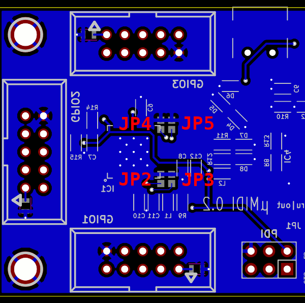
The residual pins of the MCU were connected to four jumpers on the bottom layer of the PCB. Closing a jumper results in a connection of the corresponding MCU pin to GND.
| Pin | LED |
|---|---|
| PR0 | JP2 |
| PR1 | JP3 |
| PD4 | JP4 |
| PD5 | JP5 |
Since sometimes there is no silkscreen, the jumper designators on the bottom layer are depicted below. Mind the mirrored top-layer silkscreen.

Solder jumpers
Onboard LEDs
| Pin | LED |
|---|---|
| PE0 | D7 (red) |
| PE1 | D8 (green) |
 1.8.13